Scroll down to learn about turning the dream into a reality.
THE NATURAL STANDARD
Birds navigate the skies with effortless grace, utilizing every updraft and thermal current. We aspire to capture this natural intuition, moving beyond simple mechanics to achieve a state of true, instinctual flight.
ENGINEERING GIANTS
Planes, Jets, and Helicopters are undeniable feats of engineering that have connected the globe. However, they are not the flying experience we dream of; enclosed in pressurized cabins, they lack the immersive, personal connection to the air itself.
RECREATIONAL FREEDOM
Hang gliders, wingsuits, and parasails are amazing recreational achievements that bring us a step closer to true flight. Yet, they often rely on gravity or specific weather conditions, falling short in active control, speed, and total self-propulsion.
THE MODERN FRONTIER
Innovations like the Jetson 1 and Jetman are massive modern improvements, yet they still fall just short of the true immersion and control we dream of. The FALCON is the next evolution in human flight, fulfilling these deficits to create a seamless extension of the body.
Here is how the FALCON will take us to our next evolution of human flight:
MORPHING GEOMETRY
By changing shape mid-flight, we optimize aerodynamics for the desired position, mimicking the precision of biological flight.
ULTRA-LIGHTWEIGHT
A carbon fiber skeleton and Dacron sailcloth patches will provide the wing with a light-weight and strong structure.
SAFETY MEASURES
In case of emergency, the wings will detach from the suit and pull out a parachute with it, carrying the pilot to safety.
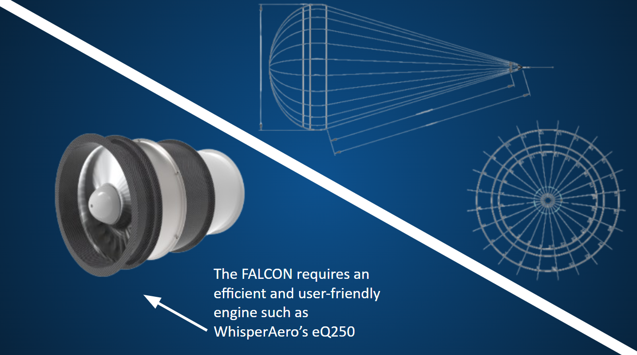
ELECTRIC THRUST
High-torque electric turbines provide necessary vertical lift without the bulk of combustion, ensuring a seamless flight profile.
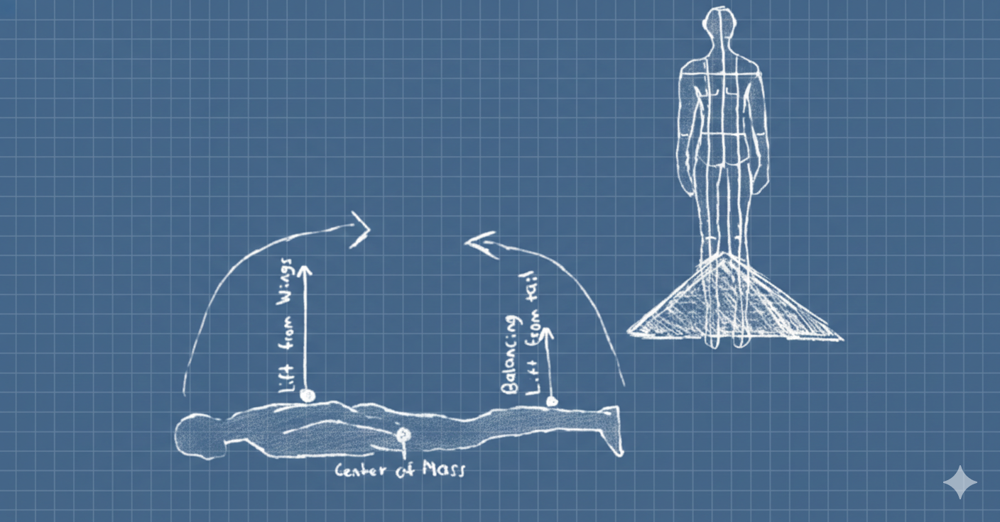
STABILIZED LIFT
The large surface area of the tail will balance the large amount of lift from the wings and eliminate unwanted instabilities.
PHYSICAL CONTROLS
The pilots physical movements will control the tail dynamics, prodividing an immersive and stable flight experience.
Explore the DESIGN and PRACTICALITY pages to learn more
DESIGN
The Engineering of Evolution
The FALCON is more than a vehicle; it is a bio-integrated flight surface. Our design philosophy focuses on removing the mechanical barriers between a human and the sky. Through morphing geometry and neural-integrated controls, we have created a concept that pushes the limits of what the human body can achieve in high-altitude environments.
Explore the four pillars of our aeronautical architecture below.
WINGS
Morphing Architecture & Lift
BODY
Propulsion & Safety Core
TAIL
Stability & Pitch Authority
SYSTEMS/UI
Immersive Controls & Experience
PRACTICALITY
From Concept to Reality
A vision of flight is only as strong as its real-world integrity. We have addressed the critical challenges of personal aviation, focusing on redundant safety measures, durable and light-weight materials, and a path to bring this design to fruition.
Explore the outline for real world implementation below.
SAFETY
Redundancy & Recovery
STRUCTURE
Long Lasting Strength & Effciency
COST
Economic Estimations & Considerations
WINGS
Morphing Architecture & Lift
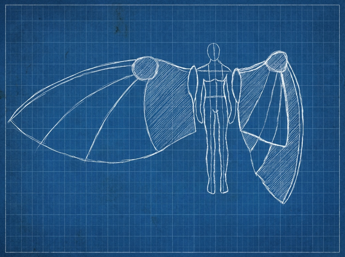
Morphing Architecture
We believe that with only one set of wings, a pilot should be able to experience easy takeoff, efficient cruising, fast dives, and quick turns. This versatility is made possible by physically morphing the wings during flight. The suit is made up of several panels coming together to work in tandem with the body unit to provide a wearable, aerodynamic shell.
Dimensional Calculations
Max Pilot Weight~100 kg
Est. Craft Weight~40 kg
Total Mass~140 kg
→
Target Wing Load25 kg/m²
Req. Surface Area5.6 m²
SA = Wing Span x Chord Lnth
→
Wing Span~4m
Avg Chord Lnth~1.4m
Mechanical Segmentation
Each wing half is divided into 4 panels; 1 stationary and 3 that make up the morphing mechanism. The stationary panel rests at the highest level with each following panel sitting just under the one before it. This allows for a aerodynamic and mechanically smooth morph.
Tension-Based Actuation
All 4 segments share a central joint. The single joint design allows the panels to rest on different levels and morph easily while maintaining effciency and simplicity. The joint utilizes heavy-duty springs to keep the wings in a natural resting position of fully extended. This acts as a additional safety measure because if there is any malfunction in the morphing mechanism, the wing pulls to the extended position providing maximum lift and thus slowing any fall.
BODY
Propulsion & Safety Core
Emergency Wing Detachment
With safety as a foremost concern, the main focus of the central section of the design is equipped with additional safety measures. In case of emergency, the back of the suit can detach the wings from the body and release a parachute.
Thrust OutputX Newtons
Run TimeX Minutes
Energy ConsumedX kWh
TAIL
Stability & Pitch Authority
The Aerodynamic Glue
The Tail is the glue that holds the whole design together. Its surface area is specifically matched to the surface area of the wings to balance and control the center of lift for the system. This results in stable flight.
Pitch Authority
The Tail also is the center of flight controls. With the ability to move up/down the tail can change the angle of attack (the pitch) of the suit in order to generate lift or initiate a dive.
SYSTEMS / UI
Immersive Controls & Experience
A detailed look into the controls for the wings, body, and tail will be added to the site soon. Stay tuned.